1. Introduction
Lockbolts are a relatively new concept to the world of fasteners, invented in the 1940s by Louis C. Huck. He developed the lockbolt concept (known at the time as the HuckBolt) for the US Navy and railcar markets to solve problems with self-loosening of conventional nuts and bolts under severe vibration. The first lockbolt patent granted in 1950 and Lou Huck founded the now widely known Huck brand.

Figure 1. The first patented lockbolt, by Louis C. Huck
The unique fastener design offered genuine solutions to common issues such as 1) loss of preload under service load, 2) setting and relaxation effects in thread, 3) self-loosening effects under vibration load, 4) relative movement in the thread bearing area. The new fastening technology quickly became popular amongst manufacturers of mechanical structures and transportation vehicles at the time, providing very welcome advantages over traditional joining methods.
Since the 1940’s, Huck engineers have expanded on the original LockBolt design to improve performance and adapt it for a wide range of nuanced applications and markets. Today LockBolts are used worldwide in a wide variety of industries by manufacturers looking to reduce maintenance of bolted joints, avoid the hazards and risks of welding, or those just looking to speed up their assembly processes.
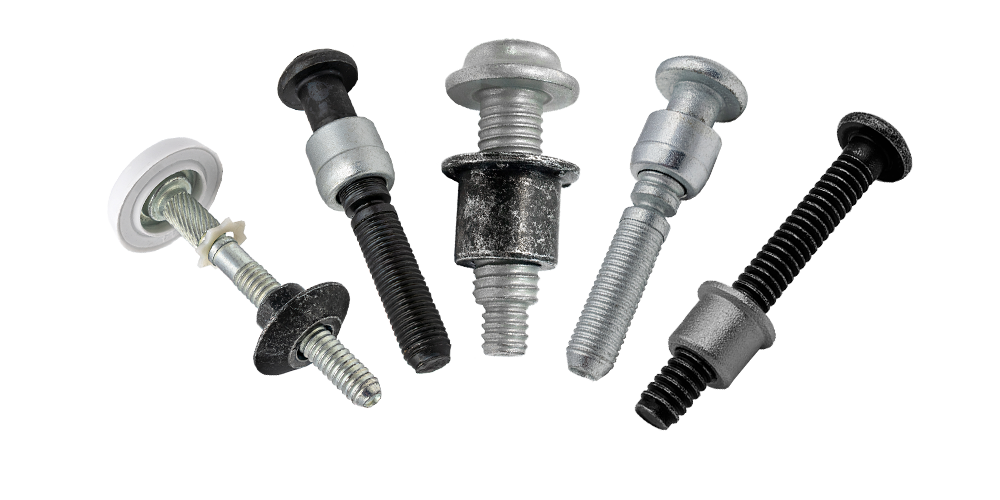
Figure 2: Different types of lockbolts
The definition of a Lockbolt:
A lockbolt is a two-piece fastener, consisting of a hardened metal pin and a metal collar. A special installation tool grips the pintail of a lockbolt and then pulls to close the gaps in the materials being joined, swaging the collar into the grooves of the pin, forming a specific, measured clamp force to hold assembled parts together.
LockBolt systems offer significant benefits to manufacturers such as: a) very quick installations, b) consistent, high clamp force, c) maintenance-free, vibration proof joints and d) excellent shear, tensile and fatigue resistance. Lockbolts are generally available in sizes ranging from 4.8mm to 36mm.
2. Designation

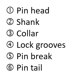
Figure 3: Designation of the main components of a lockbolt without and with pin break/break-neck
2.1 Head
The head geometry of lockbolts differs from other conventional threaded fasteners. Usually, the head of a lockbolt does not have external or internal drive features since no application of rotational force (torque) is required. The appearance depends on a) the lockbolt system and b) the application.
The truss head is the most commonly used head style for lockbolts. There are also oversized heads, which are used with softer materials, for example, or countersunk heads when a flush component surface is required.
 |
 |
 |
|||
| Flanged | Round | Truss | Brazier | Countersunk | Low-profile |
Figure 4: Common head styles for lockbolts
2.2 Shank
The shaft is usually smooth/plain or grooved. Short bolts often do not have a smooth shank. The smooth shank usually corresponds to the nominal bolt diameter and has a larger cross section than the grooved part, so that the load capacity here is particularly high.
For special applications, such as car seats, so-called shoulder bolts, where the shank has a larger diameter than the nominal diameter, are used. The shoulder bolts have a particularly high shearing capacity.
 |
 |
 |
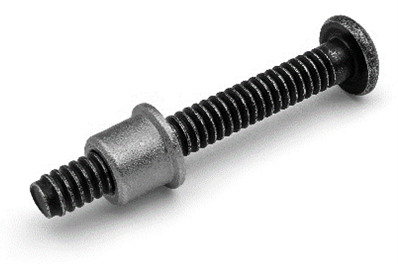
| Without plain shank | Partial plain shank | Shoulderbolt |
Figure 5: Different shank styles; without plain shank with grooves to the head, a partial plain shank and a shoulderbolt
2.3 Lock Grooves
The locking grooves are an essential feature of lockbolts and differ from conventional screws in their flatter groove geometry, which results in a larger stress cross-section with the same nominal diameter and a lower notch sharpness.
As a result, lockbolts have a significantly higher fatigue strength than threaded fasteners. The fatigue strength can be calculated according to EFB leaflet 3435-2 based on VDI-2230-1 and Eurocode 3 (EN 1993-1-9).
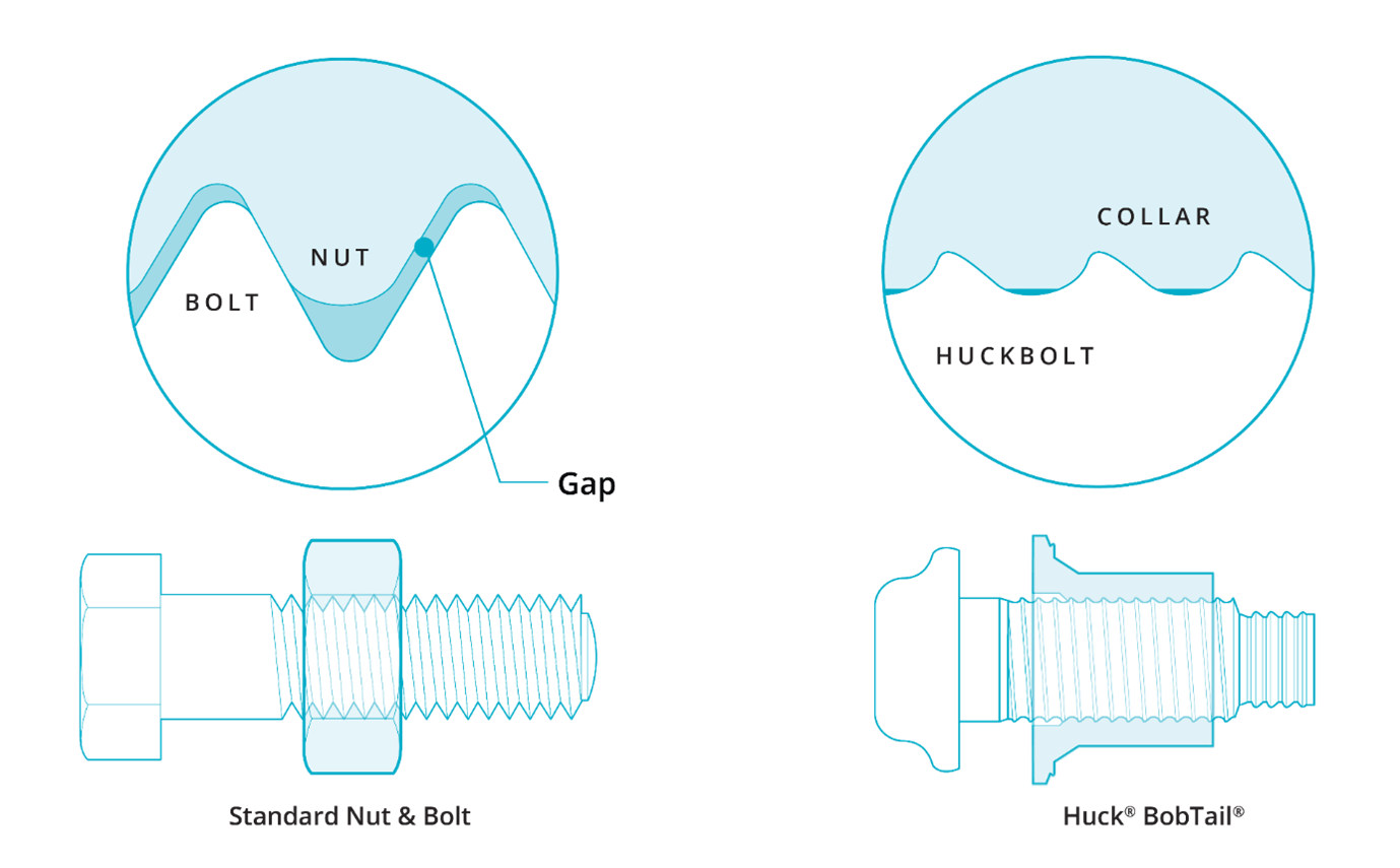
Figure 6: Comparison of threaded fasteners and lockbolt with lock grooves
2.4 Collar
Lockbolts cannot be combined with nuts to establish the connection, instead a dedicated 'collar' is used. The collar is made of a slightly softer and more ductile material than the pin. The collar is smooth (unthreaded) on the inside and, unlike a nut, is not processed by turning, but is axially pressed firmly into the grooves of the bolt by the processing tool, which generates the clamp force on the one hand and creates a non-detachable connection on the other.
Depending on the application and lockbolt type, the collar can be designed with or without a flange. If accessibility is limited, there are also variants with a lower profile to reduce protrusion. Collars must always be selected to match the lockbolt and must not be combined with other systems or processing tools.
3. Installation
3.1 Installation Tooling
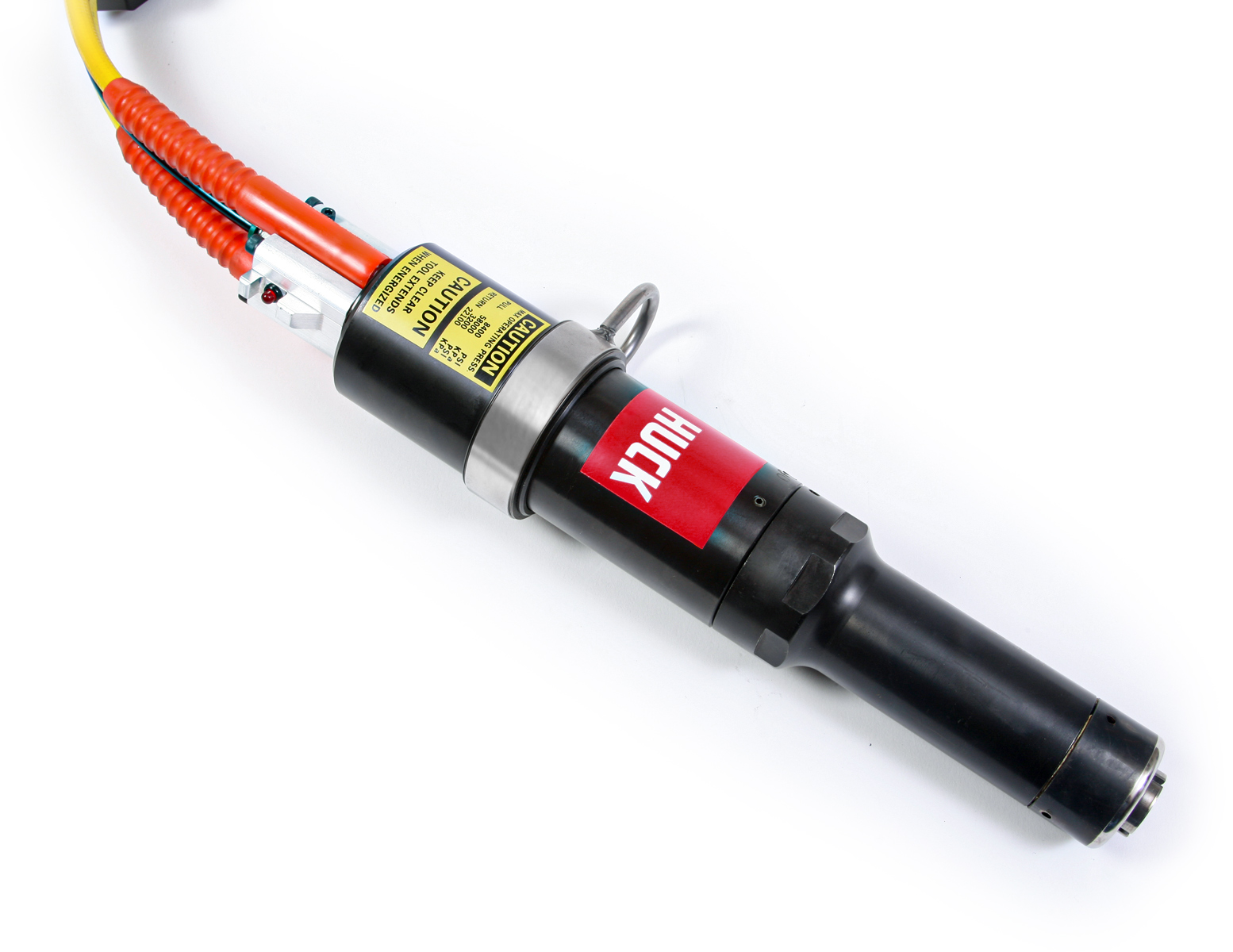
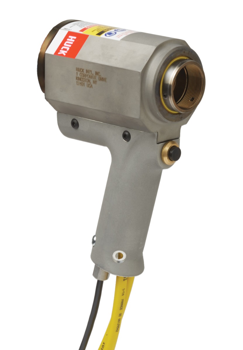
Depending on the lockbolt material and diameter, different installation tools are used. These can be hand-held devices for small diameters and small quantities. Mobile battery tools are available for sizes from 3/16’’ (4.8mm) up to M14, alternatively pneumo-hydraulic tools powered by compressed air can be used. For larger dimensions (up to M36) usually electric, diesel or battery powered hydraulic tools are used. In addition, there is the possibility of automated processing, which is often used for very large quantities in series production.
 |
 |
 |
 |
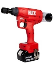 |
| BT Series | SF Series | Hydraulic Rigs | SureSet Process Control | Battery Tool |
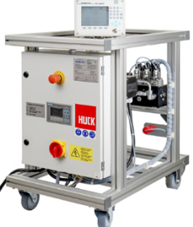
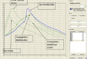
Figure 7: Tooling and process control system for lockbolts
3.2 Installation sequence
The installation process can be divided into 4 steps and can be carried out by personnel without the need for special qualifications. A basic training is usually sufficient.

Figure 8: Installation process of lockbolts with pin-break
- Insertion of the lockbolt through the clearance hole and turn the collar clockwise onto the bolt with the flange towards the component.
- Place the setting tool on the pintail and press the trigger on the tool. The clamping jaws in the anvil grasp the pintail and close the joint gap by pulling.
- By continuing to hold the tool trigger, the gripping mechanism causes the pulling head to pull over the collar and form it into the lock grooves of the pin when the required contact pressure is reached (swage load).
- The anvil of the tool retracts automatically after forming and releases the tool from the collar. The trigger on the tool can be released.
The setting process is complete with the deformation of at least one of the six indicators on the flange of the formed collar. In the case of collars without indicators, a ring gauge check can be performed to check the installation procedure. Optional installation process control can be used to monitor and document the installation process.
3.3 Visual Inspection
Inspection gauges are available from Howmet Fastening Systems and are recommended as they provide confirmation that full swaging has taken place. An example showing the use of these gauges is shown below. Ring gauges are particularly useful for collars that do not have swage indicators to assure correct installations.
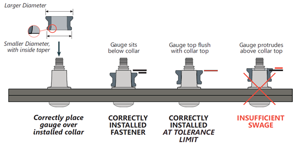
Figure 9: Visual inspection using a ring gauge
4. Materials
Lockbolt systems are traditionally made of carbon steel. Usual strengths grades for the pins are 5.8, 8.8 or 10.9 according to ISO 898-1 for metric dimensions or grade 2, 5 or 8 according to ANSI/ASME B18.2.1 for imperial sizes. In contrast to a classic nut, the collar has no strength class, since the material has to be significantly more ductile and softer in order to be able to be properly formed into the lock grooves, but is matched to the strength of the pin. Lockbolts must always be used as a set from the same manufacture.
For applications with higher demands on corrosion resistance or lightweight applications, lockbolt systems are also available made of stainless steel or aluminum. However, the bolts are generally not subject to any strength class, instead, minimum values are given for the design regarding the load-bearing capacity and clamp force.
5. Coatings
While stainless steels and aluminum alloys often do without additional coatings, the lockbolts made of carbon steel must be protected against the corrosive environment by coatings.
The type of coating and thicknesses depend on the application and requirements for corrosion resistance. The most common coatings are electroplated or organic coating systems, e.g. zinc-flake (flZn) systems, which offer a high corrosion resistance for most applications and are not susceptible to hydrogen embrittlement. Furthermore, sherardizing, or hot dip galvanizing is also available.
The corrosion resistance can often be adjusted via the layer thickness through process time and is usually tested in a neutral salt spray test (ISO 9227). If a topcoat (sealant) is applied, the corrosion resistance can be improved further. The corrosion resistance is measured in hours against red rust. In steel construction, the ISO 12944 defines corrosion resistance categories.
6. Applications
Lockbolts can be used anywhere where access to the joint from both sides is guaranteed. They represent an excellent alternative to screwed or welded connections, especially when high demands are placed on safety over the entire service life. Thus, due to their high static load-bearing capacity under shear and tensile loads and their excellent fatigue strength, lockbolts are used in many industries, from classic steel construction over renewable energies to rail and commercial vehicle construction. Some application examples are shown in the figure below.
 |
 |
 |
 |
 |
| Steel Construction / Civil Engineering | Solar | Wind | Truck / Trailer | Railcar / Rail track |
Figure 10: Applications for lockbolts
7. Design and calculation of lockbolt joints
Leaflets are readily available to assist with the design and calculation of lockbolt connections. The data sheet DVS/EFB 3435-1 from DVS (the German Association for Joining) provides a general overview of lockbolt technology. In addition, Part 2 of the leaflet (DVS/EFB 3435-2) contains the design rules for design according to VDI 2230-1 and for Eurocode 3 (EN 1993-1-3 and EN 1993-1-9).
Furthermore, Howmet Fastening Systems is the holder of a general technical approval from the DIBt (German Building Authority) for Bobtail lockbolts (Z-14.4-591) with diameter M12 up to M36.
If you have any questions about lockbolts or how they can solve challenges in your application, please get in touch to arrange a free consultation with one of our engineers.


