
1. Introduction
We’ve probably all heard the term ‘rivet’ before; that’s because the riveting concept has been around for a very long time… in fact much longer than you would expect.
As early as 2500 B.C., solid rivets were used to connect bronze parts in Greece. Although the mechanism was slightly different (achieved by deforming the cylindrical shank), the concept of riveting was born.
Blind rivets, as we recognise them today, were developed from the solid rivet. In 1916 British engineer Hamilton Neil Wylie invented and patented the first blind rivet, which allowed a single person to install a rivet with access only needed from one side. Before, installing solid rivets required access to both sides of the assembly making it a very labour-intensive, time-consuming task. The use of blind rivets freed up workers and increased production, which still represents a significant cost advantage today. (Source: https://madeupinbritain.uk/Pop_Rivet).
Blind rivets have since become a vital connecting technology in many industries.
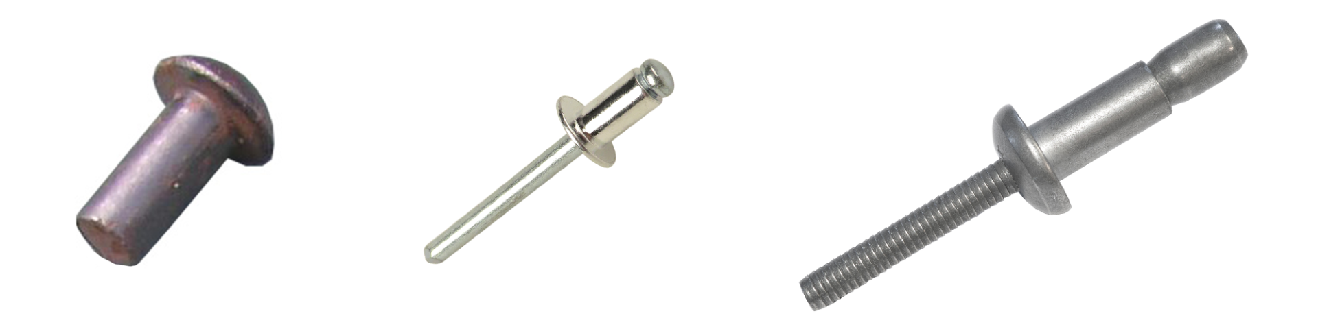
Figure 1: From left to right: ancient style bronze rivet, Wylie rivet, Huck Magna-Lok structural blind rivet.
Blind rivet definition
A blind rivet is a single-piece fastener made of two components; the body (often referred to as the sleeve) and a pin (often referred to as a mandrel). When pulling pressure is applied to the pin, the pin-head applies pressure ot the sleeve increasing its diameter on the blind side of the application fastening it in place. A simple yet effective mechanism. A structural blind rivet retains the pin in the rivet body (sleeve) post-installation for extra tensile and shear strength.
Arguably the primary benefit of blind rivets is that access is only required on one side of the application, meaning you typically only need one person to install it. The single-piece design means you just push the rivet into the hole and install it. The process is very fast, clean, and safe, delivering consistent results across the board without requiring skilled personnel.
Structural blind rivets are generally available in sizes ranging from 4.8 mm (3/16’’) up to 19.1 mm (3/4'’).
2. Designation
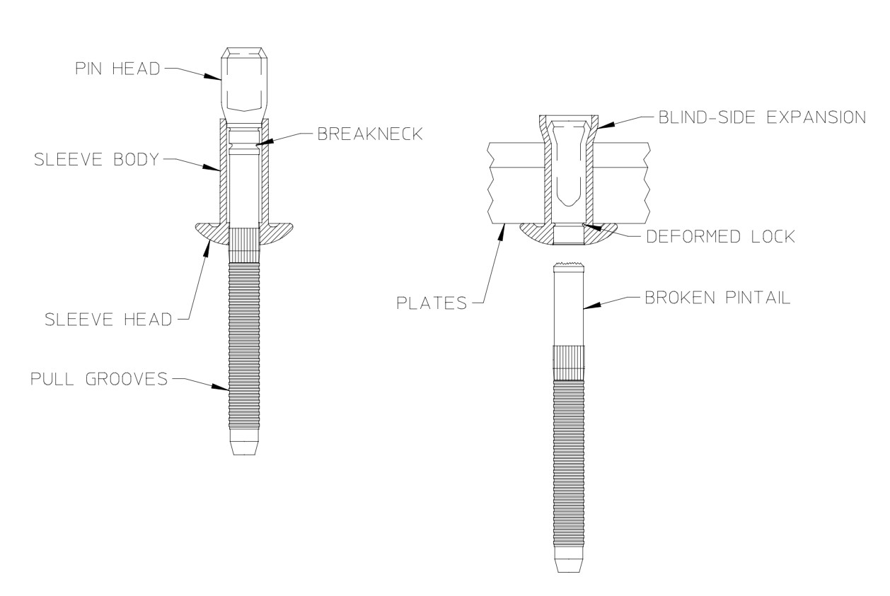
Figure 1: Designation of the main components of a blind rivet (pre-installation left, post-installation right)
2.1. Sleeve head
The blind rivet head, or sleeve head, is on the processing side of the body, i.e., on the accessible side of the connection. Diameter and shape can vary depending on the application requirements. The most common form is the flat round head (see Protruding head below). Oversized flat heads (see Truss head below) are used for example to join very soft or thin materials. Countersunk heads are used to ensure there are no protrusion, enabling a smooth component surface to reduce snag risks or drag for example.
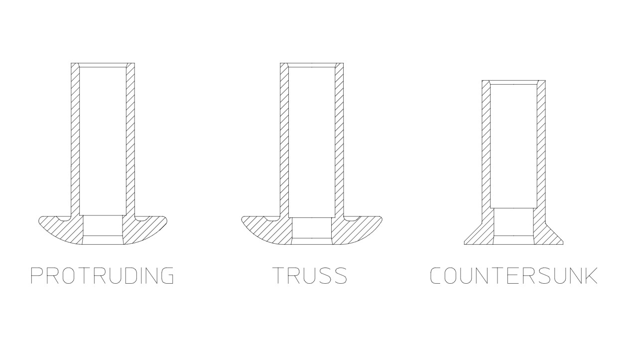
Figure 2: Common blind fastener head styles
2.2. Sleeve body
The sleeve body is the main part of the fastener behind the head that sits within the joint material (prepared hole). The sleeve body, in combination with the retained pin, determines the tensile performance of the rivet. The required sleeve body length is determined by the total material thickness to be joined (also known as the 'grip' range).
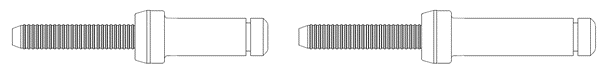
Figure 3: Short grip (left) and long grip (right)
2.3. Pin head
The pin head, or mandrel head, serves to reshape the sleeve during installation and form the blind head on the inaccessible side of the joint. As it is pulled into the sleeve it forces the sleeve to deform or expand on the blind side of the combined joint materials. The head can have different geometries depending on the blind rivet type. The most common forms of structural blind rivet types (determined by the pin head function), are 1) sleeve-expanding and 2) sleeve-bulbing blind rivets.
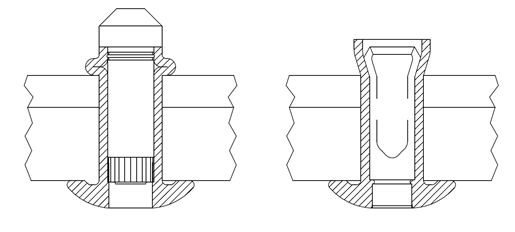
Figure 4: Sleeve folding (bulbing) blind rivet (left) and sleeve expanding blind rivet (right)
2.4. Breakneck groove
During installation the rivet pin tears off at the predetermined breaking point after the rivet body has been formed. The rivet pin breaking force is engineered to ensure it only breaks once the sleeve is correctly formed, meaning that design and manufacturing expertise is pivotal in producing rivets that install and perform consistently.
2.5. Retained pin body
The retained pin body remains in the sleeve post-installation. The contribution of the retained pin to the overall performance of the joint depend of the type of blind rivet used. Rivets where the pin breaks flush with the sleeve head, usually help to transfer external loads. Blind rivets where the pin does not break flush with the rivet head, rely on the load-bearing capacity (strength) of the rivet sleeve, since it cannot be guaranteed that the pin will absorb the loads in the joint. Manufacturing blind fasteners with consistent pin-break performance is heavily dependent on engineering and manufacturing skill which is often not seen in cheaper rivets.
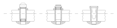
Figure 5: Broken mandrel shank for different rivet types
2.6. Broken pintail
Post-installation the broken part of the pin is fed through the nose assembly and ejected by the tool. Generally, broken pintails are collected in dedicated containers attached to the rear of the tool.
3. Installation
3.1. Installation tooling
Depending on the rivet material and diameter, the application and location of the assembly a variety of installation tools are available. Historically, pneumatic and hydraulic processing devices were required but recent advances in battery design have enabled new battery driven tools to install rivets up to 12mm in diameter (Huck BV13 / BV17). The recommended tool required to install a fastener will depend on the scenario as well the type, material and diameter of the rivets being installed.
In high volume series production applications automated processing can be used. For safety critical applications the installation process can be monitored and documented using a special hardware and software solution.
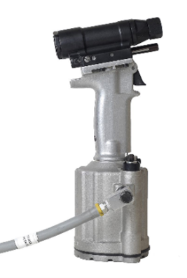
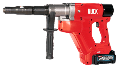

Figure 6: Pneumatic (left), electric/battery (middle) and hydraulic (right) installation tools
3.2. Installation sequence
First, the pin is placed into the pre-prepared hole(s) of the components to be joined. The nose assembly of the tool is placed over the fastener pintail and can be activated via the trigger when the head is level with the component surface.
When the tool pulls on the pintail the components are compressed between the sleeve head on the installation side of the application and the expanding sleeve on the blind side. Once the pin is permanently locked into place within the sleeve the pintail will break off, completing the installation. The process is almost instantaneous: the actual mechanical installation typically taking less than 1 second, with the complete process (including placing the rivet) usually taking a few seconds.
4. Materials
Common materials used are low-alloy carbon steels, stainless steels or aluminium alloys; in special applications other materials and alloys can also be used. Whilst the mandrel and sleeve can be made of the same or different materials, the mandrel must be harder than the sleeve to enable the body to deform during the installation. While stainless steels and aluminium alloys often do without additional surface protection, blind rivets made of carbon steel are usually protected against corrosion by coatings.
5. Coatings
Different coating types and thicknesses are available depending on the application and requirements for corrosion resistance, with the most common finishes being zinc (Zn) based electroplated coating systems. Corrosion resistance can be adjusted via the layer thickness. If a conversion layer (passivation) or a sealant / top- coat is applied, the corrosion resistance can be further improved. The corrosion resistance is generally tested in a neutral salt spray test (ISO 9227) and measured in hours.
If you have any questions about blinds rivets or about how they can work in your application, please do not hesitate to contact our engineering team who will be happy to support you.